Human Orbital Spaceflights
![]()
International Flight No. 118STS-26Discovery (7)26th Space Shuttle missionUSA |
 |
 |
 |
 |
![]()
Launch, orbit and landing data
walkout photo |
 |
|||||||||||||||||||||||||||||
alternative crew photo |
alternative crew photo |
|||||||||||||||||||||||||||||
alternative crew photo |
||||||||||||||||||||||||||||||
alternative crew photo |
||||||||||||||||||||||||||||||
Crew
| No. | Surname | Given names | Position | Flight No. | Duration | Orbits | |
| 1 | Hauck | Frederick Hamilton "Rick" | CDR | 3 | 4d 01h 00m 08s | 64 | |
| 2 | Covey | Richard Oswalt | PLT | 2 | 4d 01h 00m 08s | 64 | |
| 3 | Lounge | John Michael | MS-1, EV-2 | 2 | 4d 01h 00m 08s | 64 | |
| 4 | Hilmers | David Carl | MS-2, FE | 2 | 4d 01h 00m 08s | 64 | |
| 5 | Nelson | George Driver "Pinky" | MS-3, EV-1 | 3 | 4d 01h 00m 08s | 64 |
Crew seating arrangement
|
 |
|
||||||||||||||||||||||||
Hardware
| Orbiter : | OV-103 (7.) |
| SSME (1 / 2 / 3): | 2019 (4.) / 2022 (1.) / 2028 (1.) |
| SRB: | BI-029 / RSRM 1 |
| ET: | ET-28 (LWT-21) |
| OMS Pod: | Left Pod 04 (4.) / Right Pod 03 (8.) |
| FWD RCS Pod: | FRC 3 (7.) |
| RMS: | - |
| EMU: | EMU No. 1091 (PLSS No. 1005) / EMU No. 1090 (PLSS No. 1011) |
Flight
|
Launch from Cape Canaveral (KSC) and
landing on the Edwards
AFB, Runway
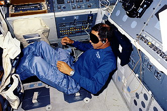
17. More than 100 mandatory modifications to the orbiter Discovery were completed before returning to flight. Major modifications include: Brake Improvements - This included changes to eliminate mechanical and thermally-induced brake damage, improve steering margin and reduce the effects of tire damage or failure. Modifications for first flight are the thicker stators, stiffened main landing gear axles, tire pressure monitoring and anti-skid avionics. 17-Inch Disconnect - A positive hold-open latch design feature for the main propulsion system disconnect valves between the orbiter and the external tank (ET) was developed to ensure that the valve remains open during powered flight until nominal ET separation is initiated. Reaction Control System Engines The RCS engines provide on-orbit attitude control and have been modified to turn off automatically in the event any combustion instability were to cause chamber wall burnthrough. Thermal Protection System - The TPS was improved in areas on the orbiter in the wing elevon cove region, nose landing gear door, lower wing surface trailing edge and elevon leading edge. Auxiliary Power Unit - An electrical interlock has been added to the APU tank shutoff valves to preclude electrical failures that could overheat the valves and cause decomposition of the fuel (hydrazine). Orbital Maneuvering System - To prevent development of leaks as a result of improper manufacturing processes, bellows in critical OMS propellant line valves have been replaced. Crew Escape System - A pyrotechnically jettisoned side hatch, crew parachutes and survival gear and a curved telescoping pole to aid the crew in clearing the wing, have been added to give a bail-out capability in the event of a problem where runway landing is not possible. An egress slide has been added to facilitate rapid post-landing egress from the vehicle under emergency conditions. This mission was the first flight of a space shuttle after the Challenger disaster. The launch was delayed for 1 hour and 38 minutes because of unseasonable and unusual light winds aloft, and to replace fuses in the cooling systems of two crew members' flight suits. The primary objective of STS-26 was to deliver NASA's second Tracking and Data Relay Satellite to orbit. In addition, several scientific experiments were carried out. The primary payload for the STS-26 mission, a Tracking a Data Relay Satellite (TDRS-C), was successfully deployed six hours after Discovery reached the orbit. The Tracking and Data Relay Satellite (TDRS-C) was the third TDRS advanced communications spacecraft to be launched aboard the Space Shuttle. TDRS-1 was launched during Challenger's maiden flight in April 1983 (STS-6). The second, TDRS-B, was lost during the Challenger accident of January 1986. TDRS-3 and its identical sister satellite supported up to 23 user spacecraft simultaneously, providing two basic types of service -- a multiple access service which can simultaneously relay data from as many as 19 low-data-rate user spacecraft, and a single access service which will provide two high-data-rate communication relays from each satellite. Transfer to geosynchronous orbit was provided by the solid propellant Boeing/U.S. Air Force Inertial Upper Stage (IUS). Separation from the IUS occurred approximately 13 hours after launch. The TDRSS satellites are the largest, privately-owned telecommunications spacecraft ever built, each weighing about 5,000 lbs. (2,267 kg) Each satellite spans more than 57 ft. (17.37 meters), measured across its solar panels. The single-access antennas, fabricated of molybdenum and plated with 14K gold, each measure 16 ft. (4.87 meters) in diameter and, when deployed, span more than 42 ft. (12.80 meters) from tip to tip. The satellite consists of two modules. The equipment module houses the subsystems that operate the satellite. The telecommunications payload module has electronic equipment for linking the user spacecraft with the ground terminal. The TDRS has 7 antennas and is the first designed to handle communications through S, Ku and C frequency bands. The Inertial Upper Stage (IUS) was used to place NASA's Tracking and Data Relay Satellite (TDRS-C) into geosynchronous orbit during the STS-26 Space Shuttle mission. The STS-26 crew deployed the combined IUS/TDRS-C payload approximately 6 hours after liftoff, at a low-Earth orbit of 160 nautical miles (296.3 kilometers). Following deployment, Discovery maneuvered to a position 36 nautical mi. (66.6 kilometers) behind and 16 nautical mi. (29.6 kilometers) above the TDRS-C/IUS before the two-stage motor ignited about 60 minutes after deployment. Upper stage airborne support equipment, located in the orbiter payload bay, positioned the combined IUS/TDRS-C into its proper deployment attitude - an angle of 58 degrees - and ejected it into low-Earth orbit. Deployment from the orbiter was by a spring-ejection system. Following the deployment, the orbiter moved away from the IUS/TDRS-C to a safe distance. The IUS first stage was fired about 1 hour after deployment. After the first stage burn of 145 seconds, the solid fuel motor was shut down. After coasting for about 5 hours, 15 minutes, the first stage separated and the second stage motor ignited at 12 hours, 29 minutes after launch to place the spacecraft in its desired orbit. Following a 103-second burn, the second stage was shut down as the IUS/TDRS-C reaches the predetermined, geosynchronous orbit position. Thirteen hours, 7 minutes after liftoff, the second stage separated from TDRS-C and performed an anti-collision maneuver with its onboard reaction control system. The IUS is 17 ft. (5.18 meters) long, 9 ft. in (2.74 meters) diameter and weighs more than 32,000 lbs. (14,515 kg), including 27,000 lbs. (12,247 kg) of solid fuel propellant. The IUS consists of an aft skirt, an aft stage containing 21,000 lbs. (9,525 kg) of solid propellant which generates 45,000 lbs. (20,411 kg) of thrust, an interstage, a forward stage containing 6,000 lbs. (2,721 kg) of propellant generating 18,500 lbs. (8,391 kg) of thrust and an equipment support section. The equipment support section contains the avionics which provide guidance, navigation, telemetry, command and data management, reaction control and electrical power. 3M Company scientists flew an experiment on STS-26 to produce organic thin films with ordered crystalline structures and to study their optical, electrical and chemical properties. They call the experiment the Physical Vapor Transport of Organic Solids (PVTOS), a name derived from the method which is employed to produce organic crystals - vapor transport. The PVTOS experiment consisted of nine independent cells 12 inches (0.3 meter) long and 3 inches (0.07 meter) in diameter. Each cell contained a test tube-like ampoule containing organic material. During space flight, the organic material was vaporized. Migrating through a buffer gas, the vaporized material formed a highly ordered thin film on a flat surface. After the samples were returned to Earth, 3M scientists studied the films produced in space. Protein Crystal Growth (PCG) experiments to be conducted during STS-26 was expected to help advance a technology attracting intense interest from major pharmaceutical houses, the biotech industry and agrochemical companies. Knowing the precise structure of these complex molecules provides the key to understanding their biological function and could lead to methods of altering or controlling the function in ways that may result in new drugs. It is through sophisticated analysis of a protein in crystallized form that scientists are able to construct a model of the molecular structure. The problem is that protein crystals grown on Earth are often small and flawed. Protein crystal growth experiments flown on four previous Space Shuttle missions already have shown promising evidence that superior crystals can be obtained in the microgravity environment of space flight. During the flight, 60 different crystal growth experiments, including as many as ten distinct proteins, was attempted in an experiment apparatus that fits into one of the Shuttle orbiter's middeck lockers. In the Protein Crystal Growth experiment, two of the 11 proteins processed - including an enzyme believed to be key to the replication of AIDS - did not produce crystals suitable for analysis. Using the same kind of invisible light that remotely controls our home TV sets and VCRs, mission specialist George Nelson was to conduct experimental voice communications with his STS-26 crewmates via infrared, rather than standard radio frequency waves (VCU (Voice Control Unit)). Six small infrared transmitters and receivers (three each) were attached by Velcro to Discovery's walls: two each on the flight deck and one each on the middeck. The transmitters and receivers are connected by cable to a base unit which also was attached by Velcro to a middeck wall. George Nelson plugged his standard lightweight headset into a belt-mounted unit which transmitted his voice via infrared lightwaves through the receivers to the base unit. There, the signal was relayed to other crew members using the standard Orbiter audio distribution system. Communications back to George Nelson from the other astronauts was travelled by the reverse path. One major objective of the experiment was to demonstrate the feasibility of the secure transmission of information via infrared light. Unlike radio frequency (RF) signals, infrared waves will not pass through the orbiter's windows; thus, a secure voice environment would be created if infrared waves were used as the sole means of communications within the orbiter. Infrared waves also can carry data as well as voice (e.g., biomedical information). Future infrared systems are expected to be smaller, lighter weight and produce better voice quality than their RF counterparts. A clear line-of-sight path was not required between transmitter and receiver to insure voice transmission. Infrared light will reflect from most surfaces and therefore, quality voice can be transmitted even after multiple bounces. As George Nelson moved around the vehicle, another major objective was to demonstrate a "flooded volume approach", that is, to see if the wall-mounted transmitters/receivers will pick up and deliver infrared signals without the need for him to precisely align his transmitter with a target receiver. Initial problems almost sidelined the tests when the voice templates that were created prior to liftoff were found to have less than 60% recognition for one crew member and less than 40% recognition for another. This problem was corrected by retraining the templates. It was retested and found to be operational with a recognition success rate of over 96%. It was concluded that weightless conditions caused a fundamental change in human speech, making the templates created prior to liftoff virtually useless. The Automated Directional Solidification Furnace (ADSF) was a special space furnace developed and managed by Marshall Space Flight Center. It was designed to demonstrate the possibility of producing lighter, stronger and better-performing magnetic composite materials in a microgravity environment. Four furnace modules were included in the ADSF, each processing a single sample. The samples being used during the STS-26 mission are manganese and bismuth composites. They were processed at a constant melting and resolidification speed of one about a third of an inch an hour. The total process times were 10.5 hours per sample. Material processed during the mission was compared with samples of the same metallic alloys processed in laboratories on Earth, as well as from previous Shuttle and sounding rocket flights. Thermal, X-ray, chemical, structural and magnetic analysis was made following the flight to determine differences in the various samples. The ADSF flight hardware was housed in three separate containers connected by power and data cables. The four furnaces were housed in one container; another container had the electronic assembly which controls furnace operations and yet another houses the control switches, status indicators and a system which records data produced during the operation of the furnaces. There were some equipment problems with the Automated Directional Solidification Furnace. Blood samples from donors with such medical conditions as heart disease, hypertension, diabetes and cancer flew in an experiment called Aggregation of Red Blood Cells (ARC) developed by Australia and managed by MSFC. The experiment was designed to provide information on the formation rate, structure and organization of red cell clumps, as well as on the thickness of whole blood cell aggregates at high and low flow rates. It shall help determine if microgravity can play a beneficial role in new and existing clinical research and medical diagnostic tests. The first ARC experiment flew aboard STS-51C in January 1985. The STS-26 experiment differed from its predecessor only in the samples tested. The experiment hardware was unchanged. The flight hardware weighed about 165 lbs. and was installed in three middeck lockers in the crew cabin. The experiment consisted of a blood pump and storage subsystem, thermal control system, pressure transducer and an electronics equipment package to provide automated control and data acquisition. The ARC experiment used eight experiment blood samples maintained at about 40 degrees F. Each flew one sample at a time, into a viscometer, two optically transparent polished glass plates separated by a spacer of platinum foil. Isoelectric Focusing (IEF) was a type of electrophoresis experiment which separates proteins in an electric field according to their surface electrical charge. The isoelectric focusing technique applied an electric field to a column of conducting liquid containing certain molecules which created a pH gradient in the column (alkalinity at one end, acidity at the other end). This pH gradient caused the biological sample to move to a location in the column where it has a zero charge - its isoelectric point. The 65-pound experiment consisted of eight glass columns containing protein, hemoglobin and albumen, with solutions which form the pH gradient column of conducting liquid. The columns were arranged in a row in the field of view of a 35 mm camera. The experiment was housed in a 9-inch-high, 19 by 21-inch (0.48 by 0.53 meter) rectangular metal container and was installed in place of a middeck locker in the crew cabin. Mesoscale Lightning Experiment (MLE) was an experiment designed to obtain night time images of lightning in an attempt to better understand the effects of lightning discharges on each other, on nearby storm systems and on storm microbursts and wind patterns and to determine interrelationships over an extremely large geographical area. The experiment used Shuttle payload bay cameras to observe lightning discharges at night from active storms. The experiment used color video cameras and a 35mm hand-held film camera and provided synoptic coverage of an area roughly 200 by 150 miles directly below the Shuttle. One of the most important aspects of biotechnical and biomedical technology involves separation processes. Cell types producing important compounds must be separated from other cell types. Cells with important biomedical characteristics must be isolated to study those characteristics. This experiment involved a separation method termed two-phase partitioning. The Phase Partitioning Experiment (PPE) was designed to fine tune understanding of the role gravity and other physical forces play in separating, i.e., partitioning biological substances between two unmixable liquid phases. Most people use to the two-phase systems formed by mixing oil and water. In PPE, the systems are simple saline solutions containing two different polymers. When the polymers are dissolved in solution, they separate. On Earth this results in the lighter phase floating on top of the heavier one. In space the demixed phases exhibit more complex behavior, looking somewhat like an egg which has a yolk floating inside of the egg white. Phase partitioning has been shown on Earth to yield more effective, large-scale cell separations than any other method, differentiating cells on the basis of their surface properties. Space experiments should improve efficiency of Earth-bound partitioning and may allow scientists to carryout cell separations unobtainable on Earth. The experiment was part of a category of handheld microgravity experiments designed to study the effects of the low gravity of spaceflight on selected physical processes. The experiment consisted of an 18-chambered experimental module filled with small quantities of two-phase systems, each differing in various physical parameters (e.g. viscosity). The module was shaken to mix the phases and the separation of the phases was photographed periodically by a mission specialist. A 15-chamber version of the PPE was successfully flown on STS-51D, and the experiment is being considered for at least two more flights. Earth Limb Radiance Experiment (ELRAD) was an experiment developed by the Barnes Engineering Co., designed to photograph the Earth's "horizon twilight glow" near sunrise and sunset. The experiment was expected to provide photographs of the Earth's horizon that will allow scientists to measure the radiance of the twilight sky as a function of the sun's position below the horizon. This information should allow designers to develop better, more accurate horizon sensors for geosynchronous communications satellites. Communications satellites routinely use the Earth's horizon or "limb" as a reference for attitude control. Barnes Engineering was developing an advanced horizon sensor that uses visible light to sense the Earth's limb. Near the spring and fall equinoxes, however, the Earth eclipses the sun once a day (as seen from the satellites' orbit), often for as long as 70 minutes. During these eclipses, the Earth's horizon is invisible to a visible light horizon sensor. However, the Earth's upper atmosphere scatters sunlight to produce a thin ring of blue and ultraviolet light that would still be visible even during an eclipse. This ring of light is what ELRAD photographed. ELRAD consisted of a 35 mm Nikon camera, an 85mm lens, a blue lens filter and a timing device known as an intervalometer. Astronauts onboard the Space Shuttle mounted ELRAD in one of the Shuttle's windows and pointed it toward the Earth's horizon. The intervalometer was set to take one photograph every 10 seconds. Three sequences of photographs were taken, one just before sunrise and two just after sunset. After the mission, the exposed film was developed by NASA and provided to Barnes Engineering, along with a sensitivity curve. Barnes Engineering then computed the radiance of the scattered light as recorded on the film. Special instrumentation to record the environment experienced by Discovery during the STS-26 mission was aboard the orbiter mounted in the payload bay. The Orbiter Experiments Autonomous Supporting Instrumentation System (OASIS) was designed to collect and record a variety of environmental measurements during various in-flight phases of the orbiter. The primary device was a large tape recorder which is mounted on the aft, port side of the orbiter. The OASIS recorder could be commanded from the ground to store information at a low, medium or high data rate. The information was used to study the effects on the orbiter of temperature, pressure, vibration, sound, acceleration, stress and strain. It also will be used to assist in the design of future payloads and upper stages. The OASIS data were collected from 101 sensors mounted on three primary elements. The sensors were located along the sills on either side of the payload bay, on the airborne support equipment of the Inertial Upper Stage and on the tape recorder itself. These sensors were connected to accelerometers, strain gauges, microphones, pressure gauges and various thermal devices on the orbiter. The damage to the thermal tiles on Discovery was very extensive and severe - the worst condition of any orbiter ever flown in the Shuttle Program. Two minor problems occurred during the flight. After ascent, the Flash Evaporator System for cooling the orbiter iced up and shut down, increasing the crew cabin temperature to approximately 87 °F (31 °C). The problem was resolved on Flight Day 4 and cooler temperatures resulted. A Ku-band antenna for communications was deployed on Flight Day 2, but it failed to respond properly and had to be stowed for the remainder of the mission. |
Photos / Graphics
 |
 |
 |
 |
 |
 |
 |
 |
 |
 |
 |
 |
 |
 |
 |
 |
 |
 |
 |
 |
| © |
Last update on May 17, 2026.  |
 |