Human Spaceflights
![]()
International Flight No. 162STS-61Endeavour (5)59th Space Shuttle missionUSA |
 |
 |
 |
||
![]()
Launch, orbit and landing data
walkout photo |
 |
||||||||||||||||||||||||||||
alternative crew photo |
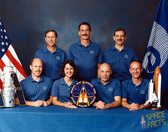
Crew
| No. | Surname | Given names | Position | Flight No. | Duration | Orbits | |
| 1 | Covey | Richard Oswalt | CDR | 4 | 10d 19h 58m 33s | 163 | |
| 2 | Bowersox | Kenneth Dwane "Sox" | PLT, RMS | 2 | 10d 19h 58m 33s | 163 | |
| 3 | Thornton | Kathryn Cordell Ryan | MS-1, EV-3 | 3 | 10d 19h 58m 33s | 163 | |
| 4 | Nicollier | Claude | MS-2, FE, RMS | 2 | 10d 19h 58m 33s | 163 | |
| 5 | Hoffman | Jeffrey Alan | MS-3, EV-1 | 4 | 10d 19h 58m 33s | 163 | |
| 6 | Musgrave | Franklin Story | MS-4, EV-2, IV, PLC | 5 | 10d 19h 58m 33s | 163 | |
| 7 | Akers | Thomas Dale | MS-5, EV-4, IV | 3 | 10d 19h 58m 33s | 163 |
Crew seating arrangement
|
 |
|
||||||||||||||||||||||||||||||||
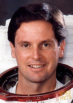
Backup Crew
|
 |
||||||||||
Hardware
| Orbiter : | OV-105 (5.) |
| SSME (1 / 2 / 3): | 2019 (13.) / 2033 (4.) / 2017 (9.) |
| SRB: | BI-063 / RSRM 23 |
| ET: | ET-60 (LWT-53) |
| OMS Pod: | Left Pod 03 (16.) / Right Pod 04 (12.) |
| FWD RCS Pod: | FRC 5 (5.) |
| RMS: | 303 (6.) |
| EMU: | EMU No. 2014 (PLSS No. 1008) / EMU No. 2026 (PLSS No. 1013) / EMU No. 2030 (PLSS No. 1014) / EMU No. 2029 (PLSS No. 1009) |
Flight
|
Launch from Cape Canaveral (KSC) and
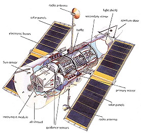
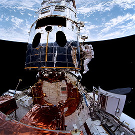
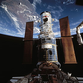
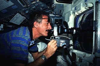
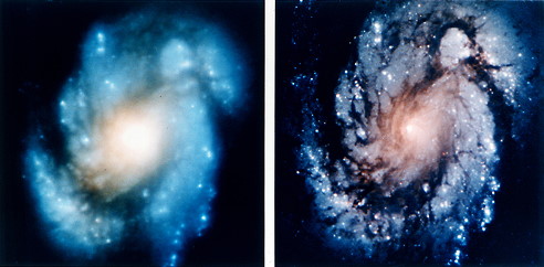
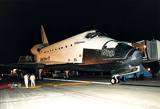
landing on Cape Canaveral (KSC), Runway 33. Endeavour was switched from Pad 39-A to Pad 39-B due to contamination of the Payload Changeout Room after a windstorm on October 30, 1993. The internal HST payload package was not affected because it was tightly sealed, and the contamination appeared to have been caused by sandblasting grit from recent Pad A modifications. On November 18, 1993 Endeavour experienced a failure of a transducer on the elevon hydraulic actuator. To change out the actuator would have required a rollback to the Orbiter Processing Facility (OPF) because access to the actuator was only through the Main Landing Gear wheel well. Since there were 4 delta-P transducers and the Launch Commit Criteria required only 3 of 4, the transducer was depinned and would not be consulted during flight. The first launch attempt on December 01, 1993 was scrubbed due to weather constraint violations at the Shuttle Landing Facility. Just before the scrub the range was also in a no-go situation due to an 800 ft (243 meters) long ship in restricted sea zone. A 24-hour scrub turn-a-round was put into effect with a launch window extending between 4:26 am to 5:38 am on December 02, 1993. Mission STS-61 was the first in a series of planned visits to the orbiting Hubble Space Telescope (HST). The first HST servicing mission had three primary objectives: restoring the planned scientific capabilities, restoring reliability of HST systems and validating the HST on-orbit servicing concept. These objectives were accomplished in a variety of tasks performed by the astronauts in Endeavour's cargo bay. Replacement of the spacecraft's solar arrays - HST's source of electrical power - was on top of the primary servicing task list. This was because solar array jitter, or excessive flexing which happens when the telescope passes from cold darkness into warm daylight, may be compromising the structural integrity of the arrays. The objective to restore the HST's science capabilities was accomplished with the installation of the Wide Field/Planetary Camera-II and the Corrective Optics Space Telescope Axial Replacement, both of which will compensate for the spherical aberration of the primary mirror. The installation of new gyroscopes, which are required to point and track HST, along with fuse plugs and electronic units increased the reliability of the HST system. The rendezvous and retrieval operational procedures for the Hubble Space Telescope were similar to those conducted on previous missions requiring capture of a free-flying satellite in orbit. Once the Shuttle was safely in orbit and the payload bay doors opened, the space support equipment activation was performed. This included activating the flight support system and orbital replacement unit carrier heaters. Other pre-rendezvous activities included checkout of the robot arm, the orbiter Ku-band dish antenna used as a radar system during rendezvous and the ground command system. The terminal initiation burn occurred about 2 hours prior to capture at a distance of approximately 40,000 feet (12,192 m) in front of the telescope. Several small mid-course correction burns followed before Commander Richard Covey took over manual control of the Shuttle about 1,200 feet (366 m) below and 500 feet (152 m) behind the telescope. On flight day 3 the orbiter approached Hubble from underneath, just after orbital sunset. This approach technique was designed to minimize potential contamination from the Shuttle's thruster firings. Prior to capture, a ground-commanded maneuver of the telescope was performed to align the grapple fixture on the HST with Endeavour's robot arm. When the telescope was grappled, using the robot arm's end effector with Claude Nicollier at the controls, it was lowered into the payload bay and berthed in the flight support system, a turntable likened to a lazy susan for its rotation and tilt ability to assist in the servicing tasks. An electrical cable was remotely attached to provide orbiter power to the telescope. The first EVA was performed by Jeffrey Hoffman and Story Musgrave on December 05, 1993 (7h 54m) to replace two sets of Remote Sensing Units (RSU) and a pair of electrical control units. The astronauts also changed out eight fuse plugs that protect the telescope's electrical circuits. After that the HST had a full set of six healthy gyroscopes. Three gyroscopes (or gyros) are required to point and track HST. Three more gyros are onboard as backups. The totals of six gyros are packaged in pairs of two, called Rate Sensing Units (RSU). One gyro failed in December 1990; a second failed in June 1991 and a third in November 1992. Two of these three gyros, one located in pair 2 and the other in pair 3, contained hybrid electronics that were suspected of causing the failures. Gyro pairs 1 and 3 also had experienced a failure in one channel of their Electronics Control Unit (ECU), the cause of which is suspected to be a random electronic part failure. While these failures have not affected HST's performance, replacing the failed hardware increased system reliability. The Rate Sensor Units were inside the housing of HST. To begin the replacement work, Jeffrey Hoffman, standing in a foot restraint mounted on the end of the Shuttle's mechanical arm, did first back out several bolts to open doors covering the star tracker near the base of HST. One of the four bolts holding the doors, called the star tracker seal, had completely removed to unlatch the doors. A programmable power wrench was used to loosen and tighten all bolts during the RSU replacement. While the arm-mounted astronaut unlatches the doors, his fellow spacewalker Story Musgrave, mounted on a foot restraint attached to a support structure in the Shuttle's bay, assisted. Once the doors are unlatched, they swung open to provide access to the bay area. The Rate Sensor Units were located behind the cone-shaped star tracker shades in the bay area of the telescope. To remove an RSU, the spacewalker, standing in an Adjustable foot restraint attached to the telescope, had to loose three bolts and disconnect two electrical plugs. The RSU then could be removed by holding a handrail located at the top of the unit. The astronauts struggled with the latches on the gyro door when two of four gyro door bolts did not reset after the astronauts installed two new gyro packages. Engineers who evaluated the situation speculated that when the doors were unlatched and opened, a temperature change might have caused them to expand or contract enough to keep the bolts from being reset. The new RSU, carried aloft in an Orbital Replacement Unit Carrier (ORUC) in the Shuttle's bay, was installed by sliding it into place and then retightening the three bolts and hooking up the two electrical plugs. The Electronic Control Units the electrical brains for the Rate Sensor Units and are located in a service bay on the Hubble Space Telescope. Once the compartment door was opened, two of the three ECUs were replaced by removing four bolts and disconnecting each one's electrical cable. The new units, which were retrieved from a protective container in the payload bay, were installed in a similar fashion. Finally, the spacewalkers also set up the payload bay for mission specialists Thomas Akers and Kathryn Thornton who would replace the telescope's two solar arrays during the second spacewalk. In anticipation of that spacewalk, Story Musgrave and Jeffrey Hoffman prepared the solar array carrier which is located in the forward portion of the cargo bay, and attached a foot restraint on the telescope to assist in the solar array replacement. In spite of the kink in array (about a panel and a half from the end), after a review by HST program managers, flight controllers decided to continue with the pre-flight plan and attempt to roll up and retract the solar arrays at the end of the first EVA. The stowage of the solar arrays is a two-step process with the initial step involving the rolling up of the solar arrays and the second step involving the actual folding up of the arrays against the telescope. Each array stands on a four-foot mast that supports a retractable wing of solar panels 12 m long and 2.5 m wide. They supply the telescope with 4.5 kW of power. Due to the problem to retract one of the solar arrays the manager decided to throw in overboard while the second spacewalk. The second EVA was conducted by Kathryn Thornton and Thomas Akers on December 06, 1993 (6h 36m), in which two damaged solar arrays were replaced. A damaged array was thrown overboard, the other one was stowed away for a return to ESA. The Solar Arrays were built in Europe under the auspices of ESA. The solar arrays provide the telescope and its instruments with 5 kW of electrical power at the start of their lifetime. They constitute the spacecraft's two "wings" and consist of 50,000 silicon photoelectric cells, covering a surface area of 84 square yards/6.6 x 39.6 x 9.24 ft (70 square meters/2 x 12 x 2.8 m). The arrays are the flexible "roll-out and roll-up" type and are made of huge sheets of plastic (fiberglass-reinforced Teflon) held in place by horizontal metal struts, which also unroll. Each wing weighed about 352 lbs. (160 kg). ESA redesigned and provided to NASA a set of spare solar arrays to reduce the jitter to an acceptable level. This set will be installed on the HST after the existing arrays are removed. To significantly reduce jitter, the new arrays have thermal insulation sleeves on the array supports, called bi-stems, to minimize heating and cooling of the support during each orbit. Springs that work like shock absorbers also will take up tension at the array ends. The new solar array was removed from the SAC by disconnecting a power and a data connection and then unlatching three latch points exactly like the latch points on the telescope. A temporary transfer handle allowed the Kathryn Thornton to carry the new array up to the installation location. Her counterpart Thomas Akers assisted with the installation by standing in a foot restraint mounted to the telescope near the work area. While the array was being transported, the power and data connectors were secured in temporary holding brackets on the array. To install the new array, first it was moved into position and once seated, the three latch points were locked in place and the connectors plugged in. The second array was replaced in exactly the same fashion. The third EVA was again performed by Jeffrey Hoffman and Story Musgrave on December 07, 1993 (6h 47m). This time the astronauts replaced two magnometers and the Wide Field Planetary Camera (WFPC). The new camera had a higher rating than the previous model, especially in the ultraviolet range, and included its own spherical aberration correction system. Following the WFPC installation, Jeffrey Hoffman changed out two magnetometers on board HST. The magnetometers, which are located at the top of the telescope, are the satellite's "compass". They enable HST to find its orientation with respect to the Earth's magnetic field. Both original units were suffering from problems of background noise. The old WFPC has been used to study bright, high-contrast objects, such as major solar system planets and nearby star clusters and galaxies. Spherical aberration, however, has hampered the ability of the camera to provide high-resolution images of the very faintest objects, or objects in a field crowded with other objects. The WFPC-II is a spare instrument developed, beginning in 1985, by the Jet Propulsion Laboratory (JPL) team, Pasadena, Calif., that built the first WFPC. When Hubble's mirror was found to be flawed, NASA and the WFPC science team immediately began working on an optical correction that could be built into WFPC-II. The new design incorporates an optical correction by the refiguring of relay mirrors already in the optical train of the cameras. Each relay mirror is polished to a new prescription that will compensate for the incorrect figure on HST's primary mirror. Small actuators will fine- tune the positioning of these mirrors on orbit, ensuring the very precise alignment that is required. The WFPC-II has three wide-field cameras and one planetary camera instead of the original total of eight. The WFPC-II team chose to reduce the number of cameras to four in order to develop a system to align the corrective relay mirrors on-orbit. Improved Charged Coupled Devices (CCDs) are incorporated into WFPC-II to improve its sensitivity, particularly in the ultraviolet. To remove and replace the Wide Field/Planetary Camera (WFPC), the doors to the service bay at the base of the telescope were opened and specially designed guide rails are installed to assist with removal of the instrument. A temporary handhold then was installed on the WFPC. Using this handhold, Jeffrey Hoffman pulled the WFPC out of its installed position while Story Musgrave watched the alignment of the WFPC on the rails and ensured it is level as it is removed. Once removed from the telescope cavity, the Jeffrey Hoffman was positioned within reach of a temporary parking fixture for the old WFPC in Endeavour's cargo bay, where it was stowed. A temporary handhold was installed on the new unit, WFPC-II, in its Scientific Instrument Protective Enclosure (SIPE) in Endeavour's cargo bay. The WFPC-II was pulled from the SIPE by Jeffrey Hoffman, who was later moved to the installation site by the arm operator Claude Nicollier. Meanwhile, the SIPE door was temporarily latched by his crew mate. Before sliding the WFPC-II into place inside the telescope, a cover over its mirror was removed. Then, Jeffrey Hoffman slided it into the telescope slot while Story Musgrave checked to ensure that it was aligned on the guide rails. Once inserted in place, the handhold was removed from the instrument and the guide rails were detached. Following the WFPC-II installation, Jeffrey Hoffman changed out two magnetometers on board HST. The magnetometers, which are located at the top of the telescope, are the satellite's "compass". They enable HST to find its orientation with respect to the Earth's magnetic field. Both original units were suffering from problems of background noise. During installation, two pieces peeled off the magnetometers. The fourth EVA was conducted by Kathryn Thornton and Thomas Akers on December 08, 1993 (6h 50m). The primary task of this EVA was to replace the High-Speed Photometer (HSP) with a device called COSTAR (Corrective Optics Space telescope Axial Replacement), which corrects the problem with the main mirror. COSTAR was designed to optically correct the effects of the primary mirror aberration on three instruments besides the WFPC: the Faint Object Camera (FOC), the Faint Object Spectrograph (FOS) and the Goddard High Resolution Spectrograph (GHRS). The FOC, provided by ESA, was designed to detect very low-luminosity celestial bodies and to provide the most detailed images on HST. It consisted of an electronic conventional scanning camera (of the television type), whose front part is a powerful image intensifier tube. Its performance has been degraded by the spherical aberration, but the sharp image cores still allowed the camera to detect details not seen by ground-based telescopes. The GHRS was intended for very detailed analysis of ultraviolet radiation. The instrument lost spectral resolution on the faintest objects, but observations of brighter sources were only moderately degraded. Through a servicing bay door, Kathryn Thornton pulled out the 487-pound (221-kilogram), phone booth-size High Speed Photometer (HSP) and installed in its place the identically sized COSTAR. Once in place, COSTAR deployed a set of mechanical arms, no longer than a human hand, that placed corrective mirrors in front of the openings that admit light into the Faint Object Camera, the Faint Object Spectrograph and the Goddard High Resolution Spectrograph. COSTAR's corrective mirrors refocused light relayed by HST's primary mirror before it enters these three instruments. COSTAR restored the optical performance of these instruments very close to the original expectations. To install COSTAR, the spacewalkers first opened doors to the bay, that enclosed the HSP, by loosening several bolts. Once the doors were open, latches that hold the HSP in place were loosened and then four electrical connectors and a ground strap were disconnected from the instrument. Then the HSP was lowered from its position to guide rails for the unit. Kathryn Thornton and Thomas Akers, standing in a foot restraint attached to the telescope, coordinated efforts to remove the device. Kathryn Thornton slided HSP out while Thomas Akers ensured that it was aligned with the guide rails. Once removed, the HSP was held by Kathryn Thornton on the end of the arm while the arm was positioned so the HSP could be placed in a temporary parking fixture mounted in the cargo bay. After it was temporarily stowed, a handhold was attached to COSTAR and it was lifted by Claude Nicollier with the RMS from its protective enclosure. A ground strap was disconnected and, while Kathryn Thornton was lifting COSTAR out, Thomas Akers was assisting by ensuring COSTAR was squarely aligned with the enclosure as it was extracted. Kathryn Thornton then was positioned up to the installation area while Thomas Akers moved to the site via handrails on the telescope. COSTAR then was aligned with the guide rails, with Kathryn Thornton watching the alignment of a rail at the upper left-hand corner of COSTAR and her counterpart checking the alignment of a rail at the lower right corner. Once COSTAR slided into place, the four electrical connections, disconnected from HSP, were connected to COSTAR along with the grounding strap, and the latches were tightened to hold COSTAR in place. The DF-224 was the HST's flight systems computer. One of the computer's six memory units had failed and another had partially failed. Hubble requires only three memory units to fully function, so the failures had not affected telescope operations. However, to restore the memory redundancy and augment the telescope's memory capacity and speed, a co- processor, based on 386-computer architecture, was integrated into the flight systems computer, which increased both flight computer memory and the speed of some operations. The DF-224 co-processor was installed on top of the HST computer located in a compartment on the telescope. The memory upgrade was installed using handles on the computer and attaching four bolts using a power tool. The fifth and final EVA by Jeffrey Hoffman and Story Musgrave occurred on December 09, 1993 (7h 21m). They replaced one of two Solar Array Drive Electronics (SADE), a very difficult work, because it was primary not planned to exchange the SADE. They also fitted an electrical connection box on the Goddard High Resolution Spectrograph (GHRS) and installed some covers on the magnometers, fabricated onboard by Claude Nicollier and Kenneth Bowersox. Each solar array wing has an electronics control assembly that includes a drive electronics unit. These units transmit positioning commands to the wing assembly. One of these Solar Array Drive Electronics units had failed due to transistor overheating. A replacement SADE, provided by ESA, should restore that lost capability and provide better heat protection for the transistors. The Solar Array Drive Electronics are mounted on the inner side of one of the doors to an HST service bay. Two electronics boxes are mounted on the inside of the door, but only one is being replaced. Once the door was opened, the two spacewalkers - one mounted on the arm and one holding handrails on the telescope - loosened six bolts to free the old SADE unit and disconnected electrical connectors attached to the unit. The new SADE unit was installed in the reverse of this process. The GHRS had two detector systems. Because of the anomalous behavior of a low-voltage power supply, the side-one detector no longer was used. The redundancy kit consisted of an externally mounted relay box that enhanced system redundancy so that the side-one detector could be used and the side-two detectors were not be compromised if the anomaly recurs. Made up of four cables and a relay box, the Goddard High Resolution Spectrograph redundancy kit was designed to bypass an erratic detector system on the science instrument located in an instrument bay on the lower portion of the HST. The relay box was installed first using a power tool similar to an electric drill. This was followed by attachment of the four cables. Flight Day 9 began on December 09, 1993, but concerns about one of HST's four onboard Data Interface Units (DIU's) delayed release. The DIUs are 35 pounds (16 kg) electronic units that transfer data between HST's main computer, solar arrays and other critical systems. A failure on Side An of DIU #2 experienced erratic current fluctuations and some data dropouts. Controllers at the STOCC and mission control came up with a troubleshooting procedure to determine the extent of the problem. HST was transferred to internal power and disconnected from its power umbilical at 16:43 UTC. Controllers then switched channels on the DIU from the A side to the B side and then back to the A side. They determined HST should be deployed. The drum brakes on the new Solar Array were applied to prevent them from vibrating during future observations. Claude Nicollier then took hold of the satellite with the robot arm. The satellite was then lifted and moved away from Endeavour. The telescope's aperture door was then reopened (a 33-minute procedure) and then released at 10:26 UTC. Commander Richard Covey and pilot Kenneth Bowersox fired Endeavour's small maneuvering jets and moved the shuttle slowly away from HST. The IMAX project is a collaboration between NASA and the Smithsonian Institution's National Air and Space Museum to document significant space activities using the IMAX film medium. This system, developed by IMAX Systems, Corp., Toronto, Canada, uses specially designed 70 mm film cameras and projectors to record and display very high definition large- screen pictures. An IMAX camera system was flown on Shuttle Mission STS-61 and was used by Endeavour's crew to collect material for upcoming IMAX productions. IMAX cameras have flown on several Shuttle missions and film from those missions was used to form the IMAX productions "The Dream is Alive" and "The Blue Planet". In-Cabin IMAX Camera Equipment was stowed in the middeck for in-cabin use. The IMAX uses two film magazines which can be interchanged as part of the operation. Each magazine runs for approximately 3 minutes. When both magazines are consumed, reloading of the magazines from the stowed supply of film is required. Lenses are interchanged based on scene requirements. The IMAX was installed in the orbiter middeck approximately 7 days prior to launch. During Shuttle Mission STS-61, an IMAX Cargo Bay Camera (ICBC) was carried in the payload bay of Endeavour and used to document activities associated with the servicing of the Hubble Space Telescope. The camera was mounted in a pressure sealed container with a viewing window. The window had a sliding door which opened when the camera was in operation. The camera was controlled from the aft-flight deck, exposing the film through a 30 mm fisheye lens. The Air Force Maui Optical Site (AMOS) tests allowed ground- based electro-optical sensors located on Mt. Haleakala, Maui, Hawaii, to collect imagery and signature data of the orbiter during cooperative overflights. The scientific observations made of the orbiter, while performing reaction control system thruster firings, water dumps or payload bay light activation, and were used to support the calibration of the AMOS sensors and the validation of spacecraft contamination models. The AMOS tests had no payload unique flight hardware and only required that the orbiter be in predefined attitude operations and lighting conditions. One of the challenges of flying long duration Shuttle missions is the issue of orbiter landing tasks. These tasks require a high level of skill and proficiency yet data shows that a pilot's landing skills degrade after an extended absence from a landing trainer such as the Shuttle Training Aircraft. During Shuttle Mission STS-61, a portable scientific workstation designed to aid the Shuttle commander and pilot in maintaining those landing skills was demonstrated. The Pilot In-Flight Landing Operations Trainer (PILOT) system hardware consisted of a portable scientific workstation, a high -resolution color display and a hand controller with orbiter look and feel. The software used in the system was transferred from the Shuttle Engineering Simulator software used to validate Shuttle flight software. This provided PILOT with orbiter handling and guidance characteristics. Due to a high-winds forecast the managers decided to bring down Endeavour one orbit earlier than planned. |
EVA data
| Name | Start | End | Duration | Mission | Airlock | Suit | |
| EVA | Hoffman, Jeffrey | 05.12.1993, 03:44 UTC | 05.12.1993, 11:38 UTC | 7h 54m | STS-61 | Endeavour | EMU No. 2014 |
| EVA | Musgrave, Story | 05.12.1993, 03:44 UTC | 05.12.1993, 11:38 UTC | 7h 54m | STS-61 | Endeavour | EMU No. 2026 |
| EVA | Thornton, Kathryn | 06.12.1993, 03:29 UTC | 06.12.1993, 10:05 UTC | 6h 36m | STS-61 | Endeavour | EMU No. 2030 |
| EVA | Akers, Thomas | 06.12.1993, 03:29 UTC | 06.12.1993, 10:05 UTC | 6h 36m | STS-61 | Endeavour | EMU No. 2029 |
| EVA | Hoffman, Jeffrey | 07.12.1993, 03:26 UTC | 07.12.1993, 10:23 UTC | 6h 47m | STS-61 | Endeavour | EMU No. 2014 |
| EVA | Musgrave, Story | 07.12.1993, 03:26 UTC | 07.12.1993, 10:23 UTC | 6h 47m | STS-61 | Endeavour | EMU No. 2026 |
| EVA | Akers, Thomas | 08.12.1993, 03:13 UTC | 08.12.1993, 10:03 UTC | 6h 50m | STS-61 | Endeavour | EMU No. 2029 |
| EVA | Thornton, Kathryn | 08.12.1993, 03:13 UTC | 08.12.1993, 10:03 UTC | 6h 50m | STS-61 | Endeavour | EMU No. 2030 |
| EVA | Hoffman, Jeffrey | 09.12.1993, 03:30 UTC | 09.12.1993, 10:51 UTC | 7h 21m | STS-61 | Endeavour | EMU No. 2014 |
| EVA | Musgrave, Story | 09.12.1993, 03:30 UTC | 09.12.1993, 10:51 UTC | 7h 21m | STS-61 | Endeavour | EMU No. 2026 |
Photos / Graphics
 |
 |
 |
 |
 |
 |
 |
 |
 |
 |
 |
 |
 |
 |
 |
 |
 |
 |
 |
|
 |
 |
 |
|
more Earth observation photos |
|
more EVA photos |
|
| © |  |
Last update on March 27, 2020.  |
 |