Human Orbital Spaceflights
![]()
International Flight No. 122STS-30Atlantis (4)29th Space Shuttle missionUSA |
 |
 |
![]()
Launch, orbit and landing data
walkout photo |
 |
|||||||||||||||||||||||||||||
alternative crew photo |
alternative crew photo |
|||||||||||||||||||||||||||||
alternative crew photo |
||||||||||||||||||||||||||||||
alternative crew photo |
||||||||||||||||||||||||||||||
Crew
| No. | Surname | Given names | Position | Flight No. | Duration | Orbits | |
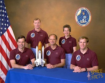
| 1 | Walker | David Mathieson | CDR | 2 | 4d 00h 56m 27s | 65 | |
| 2 | Grabe | Ronald John | PLT | 2 | 4d 00h 56m 27s | 65 | |
| 3 | Lee | Mark Charles | MS-1, EV-2 | 1 | 4d 00h 56m 27s | 65 | |
| 4 | Thagard | Norman Earl | MS-2, EV-1, FE | 3 | 4d 00h 56m 27s | 65 | |
| 5 | Cleave | Mary Louise | MS-3 | 2 | 4d 00h 56m 27s | 65 |
Crew seating arrangement
|
 |
|
||||||||||||||||||||||||
Hardware
| Orbiter : | OV-104 (4.) |
| SSME (1 / 2 / 3): | 2027 (2.) / 2030 (2.) / 2029 (2.) |
| SRB: | BI-027 / RSRM 4 |
| ET: | ET-39 (LWT-22) |
| OMS Pod: | Left Pod 01 (10.) / Right Pod 01 (10.) |
| FWD RCS Pod: | FRC 4 (4.) |
| RMS: | - |
| EMU: | EMU No. 1096 (PLSS No. 1005) / EMU No. 1095 (PLSS No. 1003) |
Flight
|
Launch from Cape Canaveral (KSC);
landing on the Edwards
AFB, Runway
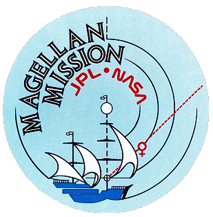
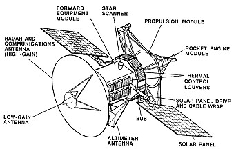
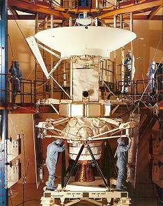
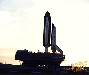
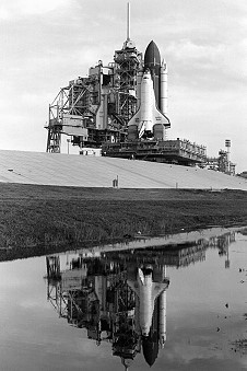
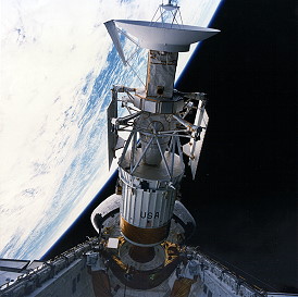
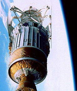
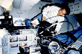
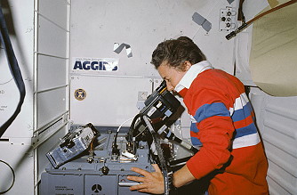
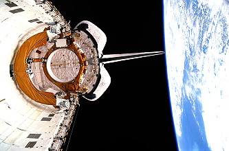
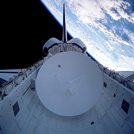
22. The launch was originally scheduled for April 28, 1989, the first day of a 31-day launch period when Earth and Venus were properly aligned, but was scrubbed at T-31 seconds because of a problem with the liquid hydrogen recirculation pump on Space Shuttle Main Engine (SSME) No. 1 and a vapor leak in the liquid hydrogen recirculation line between the orbiter and external tank. On the rescheduled liftoff date of May 04, 1989, the launch was again delayed until the final five minutes of the launch window due to cloud cover and excessive crosswinds at KSC's Shuttle Landing Facility (SLF). Good landing conditions were required at the SLF in case of a Return To Launch Site (RTLS) abort early in the flight. Main goal of this mission was the deploying of Magellan/Venus radar mapper on flight day 1. The Magellan mission mapped up to 90 percent of the surface of Venus to a high degree of resolution. The spacecraft's primary science instrument was an imaging radar, called a Synthetic Aperture Radar (SAR). In addition to mapping, precise tracking of Magellan radio signals improved our knowledge of the Venusian gravity field. Magellan was the first planetary probe to be launched from a Space Shuttle and the first planetary spacecraft to be launched in nearly 11 years. The imaging radar was capable of performing both surface imaging and altitude measurements. It was able to resolve surface features measuring from about 120 meters near the equator to about 300 meters near the north pole through the thick clouds that perpetually shroud the planet. The altimeter will measure elevations accurate to about 30 meters. Following insertion into Venus orbit in August 1990, approximately 18 days spent checking out the spacecraft and its imaging radar. The prime mapping mission then began, lasting 243 Earth days or 1 Venus day. Magellan's trajectory to Venus is called a Type IV transfer. It requires the spacecraft to go one and one-half times around the Sun before it goes into orbit around Venus. Although the Type IV transfer has advantages of lower launch energy and lower Venus approach speed, the main reason for using this trajectory is that it allows the Galileo mission to be launched by the Shuttle in May 1989, the launch time required by Magellan for the shorter and faster trajectory to Venus. In the mapping orbit, the spacecraft approached the planet as close as 155 miles (249.4 km). That is called periapsis. At its furthest point in its elliptical orbit, the spacecraft was 4,977 miles (8,009 km) from the planet's surface. That is apoapsis. Magellan made one orbit every 3 hours, 9 minutes. The approach to Venus was over the northern hemisphere with a mapping swath that goes from north to south. The radar mapping was done for a 37-minute period each orbit when the spacecraft is close to the planet, and when it was at apoapsis, it transmitted the data back to Earth. The mapping profile of Magellan included two swaths of coverage done alternatively, one beginning further north than the next. As the spacecraft approached the planet, it began mapping the north swath at 90 degrees north latitude and continue to 54 degrees south latitude. On the next orbit, it began 4.7 minutes later for the south swath and began mapping at 76 degrees north latitude and continue to 68 degrees south. As each orbit continued toward apoapsis, the spacecraft played back the data to Earth. During this time, it interrupted its playback to make star calibrations to confirm its attitude data base. Magellan looked at the positions of two stars in the sky and compares them with a star map in its computer. This fixed its attitude in relation to the planet. Then it resumed its data playback. When the second playback was completed the antenna was rotated back toward the planet for the next mapping sequence. Space Shuttle mission STS-30 deployed the Magellan Venus-exploration spacecraft into low-Earth orbit, the first U.S. planetary science mission launched since 1978 and the first planetary probe to be deployed from the Shuttle. The Magellan spacecraft was designed and constructed by Martin Marietta Astronautics Group, Denver, Colo. The height of the spacecraft is 21 feet (6.40 meters). It is 15 ft. (4.57 meters) in diameter and weighs 7,604 pounds (3,449 kg). Several subsystems make up the spacecraft system. They include the structure, thermal control, power, attitude control, propulsion, command data and data storage, and telecommunications. The high-gain antenna is used as the antenna for the synthetic aperture radar as well as the primary antenna for the telecommunications system to send data back to Earth. The 11.8-ft. (3.6 meters) diameter parabolic dish is made of strong, lightweight graphite epoxy sheets mounted on an aluminum honeycomb for rigidity. It is a spare from the Voyager project. There also is a cone-shaped medium-gain antenna used for receiving commands by and sending engineering data from Magellan during the 15-month cruise from Earth. A low-gain antenna provides the ground team with an alternative means of commanding the spacecraft in case of an emergency that prevents use of normal data rates. The altimeter antenna is mounted to one side of the high-gain antenna and is pointed vertically down at the surface of the planet during the radar data acquisitions. The forward equipment module contains the radar electronics, the reaction wheels which control the spacecraft's attitude in space and other subsystem components. The bus is a 10-sided structure consisting of the remainder of the subsystem components, including the solar panel array, star scanner, medium-gain antenna, rocket engine modules, command data and data storage subsystem, monopropellant tank and a nitrogen tank for propellant pressurization. Power for the spacecraft and the experiments is provided by two solar panels with a total area of 12.6 square meters. The array is capable of producing 1,200 watts. Both direct (dc) and alternating current (ac) are provided with dc power at 28 to 35 volts and ac power at 2.4 kilohertz. The three reaction wheels, which control the spacecraft's attitude in relation to the planet, are driven by electric motors and store momentum while they are spinning. At a point in each orbit near apoapsis, the monopropellant rocket motors are used to counteract the torque on the spacecraft as the reaction wheels are despun to eliminate the excess momentum. There is one reaction wheel for each of the spacecraft's three axes - yaw, pitch and roll. The spacecraft also has 24 thrusters used for trajectory correction and attitude control. Eight of the thrusters have 100 lbs. (45.3 kg) of thrust each. Four have 5 lbs. of thrust and 12 have 0.2 lb. (2.27 kg) of thrust. The smallest thrusters are used for attitude control and momentum unloading of the spacecraft at apoapsis. Following deployment on the first day in space, Magellan was propelled from Earth orbit in to its Venus trajectory by an Air Force-developed, Inertial Upper Stage (IUS) booster. The spacecraft cruised through space for some 15 months, including flying around the Sun, before reaching its Venus destination in August 1990. The Mesoscale Lightning Experiment (MLE) was designed to obtain nighttime images of lightning in an attempt to better understand what effects lightning discharges have on each other, on nearby storm systems, on storm microbursts and wind patterns, and other interrelationships over an extremely large geographical area. This information could lead to better Earth weather prediction models for use in airline operations and such applications as lightning early warning systems for outdoor crews of oil derricks, electrical power companies, large cranes and construction equipment. The MLE employed Shuttle payload bay cameras to observe lightning discharges at night from active storms. Using the Shuttle's payload bay color video camera augmented by a 35mm handheld still picture camera with 400 ASA film, the Shuttle cameras' 40-degree field of vision will cover an area roughly 200 by 150 nautical miles (321 by 241 km) directly below the Shuttle. The FEA-2 experiments involved five samples, three of indium with a melting point of 156 Celsius and two of selenium with a melting point of 217 Celsius. Each sample will be 1 centimeter in diameter by 19 centimeters long. The heater translation rates and process durations are given by the table on the next page. On orbit, the flight crew prepared the FEA by connecting its computer and camera. The five experiment samples were sequentially installed in the FEA at mission elapsed times of 21.5, 25.9, 30.1, 51.9 and 73.5 hours, respectively, and processed according to their unique requirements. The experiment parameters (heater power and translation rate) were controlled by the operator through the FEA control panel. The FEA was a modular microgravity chemistry and physics laboratory for use on the Space Shuttle and supports materials processing research in crystal growth, general liquid chemistry, fluid physics and thermodynamics. It had the functional capability to heat, cool, mix, stir or centrifuge experiment samples that can be gaseous, liquid or solid. Samples could be processed in a variety of containers or in a semicontainerless floating zone mode. Multiple samples could be installed, removed or exchanged during a mission through a 14.1- by 10-inch (0.36 by 0.25 meter) door in the FEA's cover. Mission Specialist Mary Cleave used a portable laptop computer to operate and monitor the Fluids Experiment Apparatus (FEA). An 8-millimeter video camcorder, flown for the first time on the Shuttle, provided the opportunity for the crew to record and downlink on-orbit activities such as the FEA, which was a joint endeavor between Rockwell International and NASA. The Air Force Maui Optical Site (AMOS) tests allowed ground- based electro-optical sensors located on Mt. Haleakala, Maui, Hawaii, to collect imagery and signature data of the orbiter during cooperative overflights. The scientific observations made of the orbiter, while performing reaction control system thruster firings, water dumps or payload bay light activation, and were used to support the calibration of the AMOS sensors and the validation of spacecraft contamination models. The AMOS tests had no payload unique flight hardware and only required that the orbiter be in predefined attitude operations and lighting conditions. The only major glitch during the flight occurred on May 07, 1989, when one of the four general-purpose computers programmed to operate the orbiter failed. The shuttle crew replaced the computer, part of a redundant set, with a backup one. It was the first time a computer had been replaced while in orbit. The glitch had no impact on the crew's safety or the primary objectives of the mission, although some of the activities involved in conducting experiments had to be canceled while the crew was replacing the computer. There also was no impact to the mission when one of the three thrusters on Atlantis' aft right-hand Orbital Maneuvering System (OMS) pod failed during ascent. However, the STS-30 crew experienced several minor annoyances. A Hasselblad camera used to photograph sites on Earth had to be stowed for the remainder of the mission after a shutter stuck during the crew's third day in space. The Text and Graphics Systems (TAGS), a device to send images and graphics to the orbiter from Mission Control, had to be turned off on Flight Day 2 because of a paper jam. Commander David Walker and Pilot Ronald Grabe had problems with a device used to take measurements of central venous pressure to determine the effects of microgravity on the cardiovascular system. On the second full day in space, the water dispensing system in the galley malfunctioned, causing some difficulties for the crew in preparing meals. Minutes before landing, the runway had to be switched from 17 to 22 due to high crosswinds. |
Photos / Graphics
 |
 |
 |
 |
 |
 |
 |
 |
 |
 |
 |
 |
 |
 |
 |
 |
 |
 |
 |
| © |  |
Last update on May 04, 2021.  |
 |