Human Orbital Spaceflights
![]()
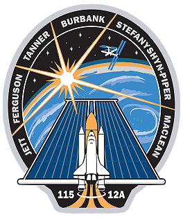
International Flight No. 246STS-115Atlantis (27)116th Space Shuttle missionUSA |
 |
 |
![]()
Launch, orbit and landing data
walkout photo |
 |
||||||||||||||||||||||||||||||||
alternative crew photo |
|||||||||||||||||||||||||||||||||
alternative crew photo |
Crew
| No. | Surname | Given names | Position | Flight No. | Duration | Orbits | |
| 1 | Jett | Brent Ward, Jr. | CDR | 4 | 11d 19h 06m 28s | 186 | |
| 2 | Ferguson | Christopher John | PLT, RMS, IV | 1 | 11d 19h 06m 28s | 186 | |
| 3 | Tanner | Joseph Richard "Joe" | MS-1, EV-1 | 4 | 11d 19h 06m 28s | 186 | |
| 4 | Burbank | Daniel Christopher | MS-2, EV-3, RMS, FE | 2 | 11d 19h 06m 28s | 186 | |
| 5 | Stefanyshyn-Piper | Heidemarie Martha | MS-3, EV-2 | 1 | 11d 19h 06m 28s | 186 | |
| 6 | MacLean | Steven Glenwood | MS-4, EV-4, RMS | 2 | 11d 19h 06m 28s | 186 |
Crew seating arrangement
|
 |
|
||||||||||||||||||||||||||||
Hardware
| Orbiter : | OV-104 (27.) |
| SSME (1 / 2 / 3): | 2044-2 (9.) / 2048-2 (6.) / 2047-2 (9.) |
| SRB: | BI-127 / RSRM 94 |
| ET: | ET-118 (SLWT-24) |
| OMS Pod: | Left Pod 04 (27.) / Right Pod 01 (34.) |
| FWD RCS Pod: | FRC 4 (27.) |
| RMS: | 301 (24.) |
| EMU: | EMU No. 3004 (PLSS No. 1004) / EMU No. 3017 (PLSS No. 1017) |
Flight
|
Launch from Cape Canaveral (KSC) and
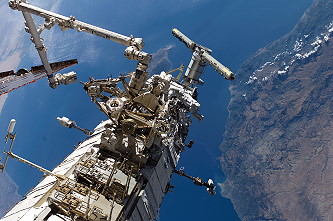
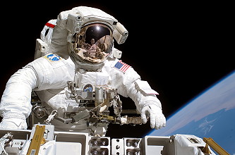
landing on Cape Canaveral (KSC), Runway 33. STS-115 was originally scheduled to launch in April 2003. However, the Columbia accident in February 2003 pushed the date back to August 27, 2006, which was again moved back for various reasons, including a threat from Tropical Storm Ernesto and the strongest lightning strike to ever hit an occupied shuttle launchpad. For the first time, NASA managers decided to move the STS-115 launch date forward to August 27, 2006 to obtain better lighting conditions to photograph the external tank. On August 28, 2006 it was decided to postpone the launch and rollback Atlantis to the VAB after updated forecasts projected Hurricane Ernesto would regain its strength and pass closer to Kennedy Space Center than previously anticipated. NASA began rolling back the shuttle on August 29, 2006 in the late morning, but by early afternoon the decision was made to move Atlantis back to the launch pad (something that has never been done before) to weather out Tropical Storm Ernesto instead. The change came after weather forecasters determined that the storm wouldn't hit Kennedy Space Center as forcefully as they once thought. Its peak winds were expected to be less than 79 mph (126 kilometers per hour), NASA's limit for keeping the shuttle outdoors. By the early morning of August 31, 2006, the storm had passed and inspection teams began a survey for damage to the launch facilities. Only three problems were discovered, all of which were simple repairs. A target date for launch was set for September 06, 2006 with the option to launch for another two days after NASA and Russian space managers agreed to extend the launch window by one day. On the morning of September 03, 2006, the official countdown began at the T minus 43-hour mark, with about 30 hours of scheduled holds. In the early morning of September 06, 2006, engineers observed an apparent internal short when one of the three electricity producing fuel cells was powered up. When engineers couldn't figure out the problem in time, the launch was scrubbed for the day to further analyze the fuel cell problem. Late Wednesday evening NASA managers decided that they would not attempt a launch on Thursday, and scheduled the next launch attempt for September 08, 2006. Originally, they had ruled out September 09, 2006 as a potential launch date due to a conflict with the planned Russian Soyuz mission Soyuz TMA-9, which was scheduled to, and did, launch on September 18, 2006. This caused some news agencies to report that Friday as the last chance for a launch until October 2006. On the morning of September 08, 2006, it was reported that one of the engine cut-off (ECO) sensors in the external tank had failed. About half an hour before the scheduled launch time, NASA announced it had decided to delay the launch for another 24 hours while the fuel was drained out of the external tank and the problem assessed. The sensor in question, ECO sensor No. 3, was proved to be faulty when it indicated that there was still liquid hydrogen in the external tank despite all of it being drained out. The other three ECO sensors correctly indicated a dry tank; and as long as they didn't start to malfunction, NASA could allow a launch with three out of the four ECO sensors operational. The mission STS-115 (ISS-19-12A ITS-P3 / ITS-P4) delivered the second port-side truss segment (ITS P3/P4), a pair of solar arrays (2A and 4A), and batteries. A total of three spacewalks were performed, during which the crew connected the systems on the installed trusses, prepared them for deployment, and did other maintenance work on the station. It was the first time in almost four years that a major new space station component, the 17.5-ton, bus-sized P3/P4 integrated truss section, has been launched. The next day after launching, Christopher Ferguson and Daniel Burbank joined Steven MacLean at the aft flight deck of Atlantis to grapple and unberth the 50-foot-long (15.2 meters) Orbiter Boom Sensor System (OBSS), a crane extension for the shuttle's robotic arm. The extension uses two lasers and a high-resolution television camera to examine the leading edges of Atlantis' wings and its nose cap for any sign of damage that may have occurred during launch. Additional inspections of the wings and other orbiter surfaces took place the day prior to undocking from the station and in the hours following undocking. Imagery analysts at the Johnson Space Center in Houston pored over the data and reported their findings to members of the Mission Management Team. While the boom inspection was under way, Joseph Tanner and Heidemarie Stefanyshyn-Piper prepared the spacesuits and tools that they, Daniel Burbank and Steven MacLean used during their spacewalks. Brent Jett and Christopher Ferguson conducted periodic firings of Atlantis' jets in the standard plan to place Atlantis on a precise course to rendezvous with the station the following day. Once the initial boom inspection was complete, the boom was put back onto the starboard sill, or edge, of the shuttle cargo bay for use later in the mission. Atlantis' approach to the International Space Station during the STS-115 rendezvous and docking process included a tricky maneuver first demonstrated on STS-114 and repeated during the STS-121 mission. The orbiter was commanded to conduct a back-flip pirouette, enabling station crew members to take digital images of the shuttle's heat shield. With Atlantis' Commander Brent Jett at the controls, the shuttle performed the 360-degree pitch-around maneuver with the orbiter about 600 feet (182.9 meters) below the station. The flip took about nine minutes to complete, offering Expedition 13 Commander Pavel Vinogradov and Flight Engineer Jeffrey Williams time to capture required tile surface imagery of Atlantis. The photos then were downlinked through the station's Ku-band communications system for analysis by systems engineers and mission managers. The photography was performed out of windows 6 and 8 in the Zvezda Service Module with Kodak DCS 760 digital cameras and 400 mm and 800 mm lenses. The imagery during the so-called Rendezvous Pitch Maneuver (RPM) or R-bar Pitch Maneuver (RPM) was among several inspection procedures instituted after the Columbia accident. The procedures were designed to detect and determine the extent of any damage the orbiter's protective tiles and reinforced carbon-carbon surfaces might have sustained. The sequence of events that brought Atlantis to its docking with the station began with the precisely timed launch of the shuttle, placing the orbiter on the correct trajectory and course for its two-day chase to arrive at the station. During the first two days of the mission, periodic engine firings gradually brought Atlantis to a point about nine-and-a-half statute miles behind the station, the starting point for a final approach. About two-and-a-half hours before the scheduled docking time on flight day 3, Atlantis reached that point, about 50,000 feet (15,240 meters) behind the ISS. There, Atlantis' jets were fired in what is called the Terminal Initiation (TI) burn to begin the final phase of the rendezvous. Atlantis closed the final miles to the station during the next orbit. As Atlantis moved closer to the station, the shuttle's rendezvous radar system and trajectory control sensor (TCS) began tracking the complex and providing range and closing rate information to the crew. During the final approach, Atlantis executed several small mid-course corrections at regular intervals with its steering jets. That placed Atlantis at a point about 1000 feet (304.8 meters) directly below the station. Brent Jett then took over the manual flying of the shuttle up the radial vector, or R-bar. The R-bar is the imaginary line drawn between the station and the Earth. He slowed Atlantis' approach and flew to a point about 600 feet (182.9 meters) directly below the station. The rendezvous was designed to optimize lighting for inspection imagery as well as crew visibility for critical rendezvous events. On verbal cue from Pilot Christopher Ferguson to alert the station crew, Brent Jett commanded Atlantis to begin a nose-forward, three-quarter of a degree per second rotational back flip. At R-bar Pitch Maneuver (RPM) start, the ISS crew began of series of photographs for inspection. The sequence of photography mapping provides optimization of the lighting conditions. Both the 400- and 800-mm digital camera lenses were used to capture imagery of the required surfaces of the orbiter. The 400-mm lens provides up to three-inch (7.6 centimeters) resolution and the 800-mm lens can provide up to one-inch (2.5 centimeters) resolution as well as detect gap filler protrusions of greater than .25 inch (6.4 mm). The imagery includes the upper surfaces of the shuttle as well as Atlantis' belly, capturing pictures of the nose landing gear door seals, the main landing gear door seals and the elevon cove with one-inch analytical resolution. Since the STS-114 mission, additional zones were added for the 800-mm lens to focus on the gap fillers on Atlantis' belly when the orbiter is at 145 and 230 degree angles during the flip. There should be enough time for two sets of pictures. When Atlantis completed its rotation, it returned to an orientation with its payload bay facing the station. Brent Jett then moved Atlantis to a position about 400 feet (121.9 meters) in front of the station along the V-Bar, or the velocity vector, the direction of travel for both spacecraft. Christopher Ferguson provided Brent Jett with navigation information as he slowly inched the shuttle toward the docking port at the forward end of the station's Destiny Laboratory. Christopher Ferguson joined mission specialists Joseph Tanner, Daniel Burbank and Heidemarie Stefanyshyn-Piper in playing key roles in the rendezvous. They operated laptop computers processing the navigational data, the laser range systems and Atlantis' docking mechanism. Using a view from a camera mounted in the center of Atlantis' docking mechanism as a key alignment aid, Brent Jett precisely matched up the docking ports of the two spacecraft. He flew to a point where the docking mechanisms were 30 feet (9.14 meters) apart and paused to check the alignment. For Atlantis' docking on September 11, 2006, Brent Jett maintained the shuttle's speed relative to the station at about one-tenth of a foot per second (while both Atlantis and the station were traveling at about 17,500 mph = 28,163 km/h), and kept the docking mechanisms aligned to within a tolerance of three inches. When Atlantis made contact with the station, preliminary latches automatically attached the two spacecraft. Immediately after Atlantis docked, the shuttle's steering jets were deactivated to reduce the forces acting at the docking interface. Shock absorber-like springs in the docking mechanism dampened any relative motion between the shuttle and the station. Once that motion between the spacecraft had stopped, Joseph Tanner secured the docking mechanism, sending commands for Atlantis' docking ring to retract and to close a final set of latches between the two vehicles. When Atlantis arrived at the station two days after its launch, the six-person shuttle crew was greeted by the three-man Expedition 13 crew. Russian Commander Pavel Vinogradov and Flight Engineer and NASA Science Officer Jeffrey Williams have been aboard the complex since April 01, 2006 following their launch on the Soyuz TMA-8 spacecraft from the Baikonur Cosmodrome in Kazakhstan. They were scheduled to return to Earth in late September following the arrival of the next station crew, Expedition 14, which launched in Soyuz TMA-9 spacecraft right after the STS-115 mission. The third member of the Expedition 13 crew is European Space Agency astronaut Thomas Reiter who arrived at the outpost on the STS-121 mission. He remained on board with the Expedition 14 crew through the end of the year 2006. Following docking, Christopher Ferguson and Daniel Burbank attached the shuttle's robotic Canadarm to the 17.5-ton P3/P4 truss, lifted it from its berth in the payload bay, and maneuvered it for handover to the station's Canadarm2. The P3/P4 truss segment provides an additional photovoltaic module (PVM) with two power channels (2A and 4A), the port Solar Alpha Rotary Joint (SARJ) and two Unpressurized Cargo Carrier Attachment System sites. The P3/P4 segment is 45.3 ft (13.8 meters) long and weighs 34,885 pounds (15,823 kg). The P3 structure has an elongated hexagonal cross section with two bays arrayed along the long axis. The P4 truss segment is integrated to the P3 segment before flight. The Solar Alpha Rotary Joint (SARJ) enables the new outboard solar arrays to always point to the sun by rotating like a Ferris wheel. The port SARJ on P3/P4 provides tracking for the P4 and P6 solar arrays once P6 is relocated to P5 on the STS-120 mission. The starboard SARJ for the S3/S4 arrays, to be delivered on STS-117, will provide tracking for the S4 and S6 solar arrays once S6 is installed on the STS-119 mission. The SARJ can rotate 360 degrees clockwise and counterclockwise. The SARJ also provides the structural interface between the P3 or S3 and P4 or S4 elements. It includes hardware to route power and data through the rotating SARJ interface to the outboard truss segments. The SARJ includes an inboard and an outboard race ring, which provide the structural connection between the P3 and P4 elements. Along the circumference of each race ring are gear teeth that mesh with the drive lock assembly (DLA) pinion gear to rotate the SARJ. The outboard race ring is used by the DLA for rotating the SARJ. The 12 equally-spaced trundle bearings hold the SARJ inboard and outboard race rings together. Each trundle bearing is fixed to the inboard race ring and is clamped onto the outboard race ring with a roller interface to allow for SARJ rotation. There are three rollers on the trundle bearing that interface with the outboard race ring; the inner and outer upper rollers and the center roller. Each roller consists of two bearings: the primary and journal bearings. The primary bearing rotates. If the primary bearing seizes up, the journal bearings will begin rotating. The journal bearing is designed to operate for about 30 days. There are micro-switches in the trundle bearing that allow the ground to know if the journal bearing is rotating. Two Drive Lock Assemblies (DLAs) are responsible for rotating and locking the SARJ. Each DLA includes the engage-disengage mechanism (EDM) motor, drive motor, pinion gear, lock rack and two follower arms. The EDM motor is a stepper motor that pivots the lock rack and pinion gear about the lock/engage pivot point to the desired position. The DLA positions are locked, engaged and neutral. For the locked position, the lock rack is in contact with the race ring gear teeth to prevent the SARJ from rotating. For the engaged position, the DLA pinion gear is meshed with the race ring gear to rotate the SARJ with the drive motor. In the neutral position, neither the lock rack nor pinion gear is engaged to the race ring gear. The follower arms, which are of the same design as the trundle bearings, are used to secure the DLA to the race ring. The two rotary joint motor controllers (RJMCs) are mounted on the structural ribs of the inboard race ring and control the operation of the DLA motors via commands from the P3 multiplexers/demultiplexers (MDMs). Each RJMC has two heaters and a resistive thermal device sensor monitored by the P3 MDMs. The RJMC supplies and receives voltage signals from the resolvers on the Utility Transfer Assembly to determine the position of the SARJ (resolver A is connected to RJMC 1, resolver B is connected to RJMC 2). For SARJ outboard operations, one RJMC is moved to the outboard race ring. At launch, the SARJ is secured with 16 launch locks and 10 launch restraints. All the launch locks and the six outboard launch restraints will be removed on orbit before the SARJ is rotated, first in a short test, then in its operational configuration. On the longerons for two sides of the SARJ, there are stub rail segments that bridge over the interface that enables the SARJ to rotate. The launch restraints on the inboard and outboard side hold the stub rail segments in place. When the SARJ is operating in the inboard mode, the outboard launch restraints are removed and the inboard launch restraints are left in place so that the stubs rails are cantilevered over the rotating SARJ interface. The SARJ inboard bulkhead is structurally attached to P3 at the P3 longerons and four SARJ braces. The braces are stowed on the diagonals and not connected to the inboard bulkhead for launch so that the SARJ loads path is supported entirely by the launch restraints. The major components of the P4 truss are the port inboard photovoltaic module and modified Rocketdyne truss attachment system. The P4 photovoltaic module contains two power channels, 2A and 4A. The P4 element includes the active side of the P4/P5 Modified Rocketdyne Truss Attachment System (MRTAS), which will be used to attach the P5 element to P4 on the next shuttle mission, STS-116. Unlike the other type of attachment system that mated the P6 array truss to the Z1 truss and will be used to attach P6 to P5, the MRTAS does not include a capture claw since, due to the P4 BGA locations, there is no room to accommodate it. The P5 is soft-docked to P4 by positioning the four P5 coarse cones (one on each corner) into receptacles on P4. Once the P5 element is soft-docked, the crew secures the primary bolt at each corner on P5 into the nut assemblies on P4. If the primary bolt cannot be secured, two contingency bolts at each corner on P5 can be tightened into the nut assemblies on P4. The first EVA was performed by Joseph Tanner and Heidemarie Stefanyshyn-Piper on September 12, 2006 (6h 26m) for installation of power and data cables between the P1 and P3/P4 structures in preparation for solar array deployment. During the first EVA, the crew prepared the truss for activation and prepared the solar arrays for deployment. As Joseph Tanner and Heidemarie Stefanyshyn-Piper prepared for the spacewalk, Steven MacLean and Jeffrey Williams used the station's robotic arm to slowly move the 17-and-a-half ton P3/P4 truss to the port side of the integrated truss system. They aligned it using a television camera and then mate it to P1. Once Joseph Tanner and Heidemarie Stefanyshyn-Piper had left the airlock, they moved to the newly installed truss. Upon a "go" from Mission Control that the proper electrical inhibits are in place, Joseph Tanner connected the power cables in the P1-to-P3 lower utility tray, where the electrical connections are housed. He also closed the number 7 Circuit Interrupt Devices. Upon completion, Joseph Tanner gave the ground control team a "go" to begin the activation of the P3/P4 truss. Heidemarie Stefanyshyn-Piper also was working on the P3/P4 truss. Her first task was to release the aft and forward Solar Array Blanket Box (SABB) launch restraints, unbolting the SABBs from the Integrated Equipment Assembly. The SABBs hold the folded solar arrays. Heidemarie Stefanyshyn-Piper released the aft SABB first. Heidemarie Stefanyshyn-Piper and Joseph Tanner then released similar restraints for the Beta Gimbal Assemblies (BGA). The BGAs are the structural link between the truss' integrated electronics and the Solar Array Wings. Heidemarie Stefanyshyn-Piper released the forward wing BGA; Joseph Tanner released the aft wing BGA. Prior to the forward wing BGA release, Joseph Tanner rotated a keel pin that held the P4 truss segment in place for launch. Joseph Tanner and Heidemarie Stefanyshyn-Piper then completed unstowing the SABBs. Next, the spacewalk crew began preparing the Solar Alpha Rotary Joint (SARJ) for rotation by installing the drive lock assemblies (DLA) to their on-orbit position. Heidemarie Stefanyshyn-Piper also deployed and rigidize the four Alpha Joint Interface Structure (AJIS) struts. The AJIS struts must be rigidized, for purposes of structural loading, prior to removing any of the launch locks on the subsequent EVA. When Mission Control had completed the P3/P4 activation to a point where the next set of electrical inhibits are in place, Joseph Tanner connected the electrical cables in the P1-to-P3 upper utility tray. He also removed the number 6 and 8 Circuit Interrupt Devices in preparation for work on the next shuttle flight, STS-116. With the conclusion of the spacewalk, Mission Control Houston commanded the activation of the P4 truss to check out its systems and the still folded solar arrays. The BGAs rotated to the correct position for the deployment of the solar arrays on flight day 6. The second EVA by Daniel Burbank and Steven MacLean occurred on September 13, 2006 (7h 11m) to continue work to prepare the International Space Station’s P3/P4 integrated truss for operation; Steven MacLean became the first Canadian to perform an EVA. Daniel Burbank and Steven MacLean continued preparing the SARJ for rotation by releasing and removing 16 launch locks, six of 10 outer launch restraints. The launch locks and launch restraints constrain the SARJ and handle loads during ascent. All of the launch locks had to be removed before any of the launch restraints could be removed. In addition, the drive lock assemblies had to be deployed to provide a method of controlling uncontrolled SARJ rotation. Both Daniel Burbank and Steven MacLean worked simultaneously to remove the launch locks. Each launch lock was located under a separate insulation cover which is in turn connected to the SARJ inboard bulkhead by four to six bolts, and connected to the outboard bulkhead by one to three spring-loaded clamp bolts. The cover had to be removed to access the launch lock. After removing the cover, the launch lock was removed by releasing four bolts. Once the launch lock was removed, the cover was replaced and reattached to the SARJ inboard bulkhead. The outboard spring clamp bolts were left open to allow for SARJ rotation. After the launch locks were removed, Daniel Burbank and Steven MacLean began removing the SARJ launch restraints. These restraints hold together the inner and outer SARJ bulkheads. There are two additional launch restraints holding the forward face nadir and zenith SARJ stub rails to the inboard SARJ bulkhead as well as two additional launch restraints on aft truss beams. The final task of EVA 2 was the deployment of the SARJ brace beams. These beams are located on the P3 inboard side of the SARJ. These beams also help rigidize the SARJ interface. Once these tasks were completed, the SARJ could be rotated and Mission Control commanded a checkout that involved as series of tests, including rotating the SARJ a full 360 degrees, plus another 180 degrees to position the P4 photovoltaic radiator (PVR) pointing toward Earth. This position corresponds to the 0-degree SARJ position. Day 6 continued the installation of the solar array. The unfurling of the solar panels themselves began a little behind schedule due to the problem encountered on Day 5 with SARJ. This problem was determined to be in the software, and a workaround was developed. The unfurling of the panels continued throughout the morning in stages to prevent the panels sticking, as they did during STS-97. It was still noted by the crew that some of the panels were sticking together, but this didn't cause any problems. Although the installation has been completed, the solar arrays will not provide power to the station until the next shuttle mission, STS-116, scheduled for December 2006, when the station will undergo a major electrical system rewiring. The third and final EVA by Joseph Tanner and Heidemarie Stefanyshyn-Piper occurred on September 15, 2006 (6h 42m) to perform final tasks required for activation of the Solar Alpha Rotary Joint (SARJ). The SARJ is an automobile-sized joint that will allow the station's solar arrays to turn and point toward the sun; they also prepared the P3/P4 truss and its solar arrays for operation by setting the stage for deployment of the truss' radiator. Joseph Tanner had performed than 7 EVA's in his career. Later on, the solar arrays were fully unfolded. Heidemarie Stefanyshyn-Piper retrieved the materials on the International Space Station Experiment 5. The materials science experiment tests the effects of the space environment on prospective spacecraft materials. During the EVA, the crew installed bolt retainers on the P6 beta gimbal assembly (BGA), prepared the P4 PVR, a photovoltaic or heat-dissipating radiator, for deployment, cleared the path on P3's forward face for the MT's move to work site 8, removed and replaced the S1 S-band antenna support assembly (SASA), removed and replaced the string 1 baseband signal processor (BSP) and transponder on the S1 truss, installed the antenna group interface tube (AGIT) heat shield, and retrieved the Materials for ISS Experiment (MISSE) 5 from P6. Before moving to P4, Joseph Tanner moved to the P6 zenith bulkhead to install eight bolt retainers on the P6 beta gimbal assemblies and engaged a remaining P6 4-bar hinge lock. The bolt retainers will prevent the potential backing out of those bolts. One of the eight hinge locks did not engage during the STS-97 mission. Although previous attempts to engage the lock were unsuccessful, the team believes they have the correct tool for the non-standard task. Heidemarie Stefanyshyn-Piper spent some time preparing the work sites for the SASA task. The crew then moved to P4 where they prepared the P4 radiator for deployment by removing the cinches and winches on the radiator. These must be released before the crew inside the station can deploy the radiator. The cinches are wire braided cables with nut assemblies on the end that serve as launch restraints for the PVR. One end of the cable is permanently attached to the PVR base plate, the opposite end contains an adjustable nut assembly that slides into a receptacle on the outermost PVR panel. The nut assemblies secure the PVR for launch. The EVA crew used a pistol grip tool (PGT) on the nuts to release the tension in the cable, removed the cable nut assembly from its receptacle on the PVR, and attached the cinch to a clip on the PVR base plate. The next task was to release the winch bar, which secured the PVR during launch, from the PVR. A PIP pin secures the winch bar to the outermost PVR panel. Joseph Tanner released one of the winch PIP pins while Heidemarie Stefanyshyn-Piper released the other. After the winch bar was released from the PVR, the pip pin was reinstalled into the winch bar. The radiator then was ready for deployment. Joseph Tanner and Heidemarie Stefanyshyn-Piper also "cleared" the P3 forward face so the mobile transporter (MT) can move onto the P3 truss. The keel pin and drag link are located on P3 face 1. Joseph Tanner and Heidemarie Stefanyshyn-Piper removed the drag link and keel pin and stowed them within the P3 structure. Joseph Tanner and Heidemarie Stefanyshyn-Piper removed the P3 space vision system (SVS) target, as well as rotated P1, P3 MT stops and tether shuttle stops. In addition, the crew installed the EVA temporary rail stop (ETRS). The ETRS now performed the functions of the other MT and tether shuttle stop mechanisms while still allowing a Crew and Equipment Translation Aid (CETA) cart to be outboard of the MT/MBS while the MT/MBS is at the P3 work site. The crew also relocated the articulating portable foot restraints (APFR) used during their tasks to the P4 truss where they not interfered with the MT movement. After completing their P3 and P4 tasks, Joseph Tanner and Heidemarie Stefanyshyn-Piper moved back to the Z1 truss via the airlock. The EVA crew started working on the removal and replacement of the SASA on S1 with a spare unit that is located on the Z1 truss. The task required several handoffs between the crew to move the spare SASA up to the S1 truss. The crew also needed to temporarily stow the failed SASA while the spare SASA is installed. The crew reversed their path and used the same technique to move the failed SASA back to the Z1 truss. The failed SASA were returned to Earth on a later mission. Heidemarie Stefanyshyn-Piper retrieved upgraded S-band BSP and transponders from the airlock. The new Orbital Replacement Units (ORUs) were carried to the work site in a large ORU transfer bag. Heidemarie Stefanyshyn-Piper temporarily stowed the bag on the S1 truss while she changed out the S-band transponder and base-band signal processor (BSP). She returned to the airlock with the older version BSP and transponder. While Heidemarie Stefanyshyn-Piper was busy on the S1 truss, Joseph Tanner installed a heat shield on the Ku-band antenna group interface tube (AGIT). This will help prevent over heating in this area during certain ISS attitudes. Joseph Tanner then returned to the P6 truss to remove MISSE 5 from the P6 truss for return to Earth. Other work of the crew was: a talk of Steven MacLean with the Canadian Prime Minister Stephen Harper and other press meetings, transferring cargo, including water, between the shuttle and the space station, removal of the REBA, Rechargeable EVA Battery Assembly, photo shootings There were two experimental payloads that were carried to the station on STS-115. The experiments were left for the station crew to perform. The objective of the Effect of Spaceflight on Microbial Gene Expression & Virulence (MICROBE) payload was to characterize the effects of space on the virulence and physiology of three common microbes previously isolated from the space shuttle environment and to facilitate development of effective antimicrobials/therapeutics and effective systems for maintaining water potability. The Yeast-GAP experiment studied how individual genes respond to microgravity conditions. The results could help scientists understand how mammalian cells will respond when they are grown in microgravity as well as improve culturing techniques of mammalian cells on Earth. With additional inspections of Atlantis' heat shield the day before undocking, and immediately post undocking, the orbiter undocked with the shuttle robotic arm and Orbiter Boom Sensor System (OBSS) deployed in their mated configuration. The OBSS was stowed after the inspections are completed. Once Atlantis was ready to undock, Joseph Tanner sent a command to release the docking mechanism. At initial separation of the spacecraft, springs in the docking mechanism pushed the shuttle away from the station. Atlantis' steering jets were shut off to avoid any inadvertent firings during the initial separation. Once Atlantis was about two feet (61 centimeters) from the station, with the docking devices clear of one another, Christopher Ferguson turned the steering jets back on and fired them to very slowly move away. From the aft flight deck, Christopher Ferguson manually controlled Atlantis within a tight corridor as the orbiter separated from the station, essentially the reverse of the task performed by Brent Jett just before Atlantis docked. Atlantis continued moving away to a distance of about 450 feet (137.2 meters), where Christopher Ferguson initiated a maneuver to fly the shuttle directly above the station. Once Atlantis reached that point, Christopher Ferguson fired Atlantis' jets to depart the vicinity of the station for the final time. Atlantis separated to a distance of about 40 nautical miles (74 km) from the station. The shuttle remained there to protect for a return to the complex in the unlikely event the late inspection reveals any damage to the heat shield. After undocking from the ISS, the heat shield was again inspected; additional inspections were necessary, when a video from cameras aboard the shuttle showed a piece of debris in close proximity to the vehicle, but engineers found no issues of concern during the survey. Following the review of these scans, together with an overnight analysis of the payload bay by Ground Flight Controllers, it was determined that there remained no safety issue with Atlantis, and Mission Controllers cleared the Orbiter for re-entry. This clean bill of health, added to a favorable weather forecast for the Shuttle Landing Facility for next morning, permitted Atlantis to be cleared for a landing the next day. |
EVA data
| Name | Start | End | Duration | Mission | Airlock | Suit | |
| EVA | Tanner, Joseph | 12.09.2006, 09:17 UTC | 12.09.2006, 15:43 UTC | 6h 26m | STS-115 | ISS - Quest | EMU No. 3004 |
| EVA | Stefanyshyn-Piper, Heidemarie | 12.09.2006, 09:17 UTC | 12.09.2006, 15:43 UTC | 6h 26m | STS-115 | ISS - Quest | EMU No. 3017 |
| EVA | Burbank, Daniel | 13.09.2006, 09:05 UTC | 13.09.2006, 16:16 UTC | 7h 11m | STS-115 | ISS - Quest | EMU No. 3008 |
| EVA | MacLean, Steven | 13.09.2006, 09:05 UTC | 13.09.2006, 16:16 UTC | 7h 11m | STS-115 | ISS - Quest | EMU No. 3006 |
| EVA | Stefanyshyn-Piper, Heidemarie | 15.09.2006, 10:00 UTC | 15.09.2006, 16:42 UTC | 6h 42m | STS-115 | ISS - Quest | EMU No. 3017 |
| EVA | Tanner, Joseph | 15.09.2006, 10:00 UTC | 15.09.2006, 16:42 UTC | 6h 42m | STS-115 | ISS - Quest | EMU No. 3004 |
Photos / Graphics
 |
 |
 |
 |
 |
 |
 |
 |
 |
 |
 |
 |
 |
 |
 |
 |
 |
|
more EVA photos |
|
| © |  |
Last update on March 27, 2020.  |
 |